MoCA Wiring Diagram: How to Connect Adapters, Splitters, Filters, and Mesh
On this page
A good MoCA wiring diagram is less about drawing every wall plate and more about proving one thing: the router-side MoCA adapter and the room-side adapter must sit on the same coax tree, with MoCA-rated splitters between them and the PoE filter at the edge of the home.
Quick answer
The standard MoCA wiring pattern
- Router LAN port → Ethernet → main MoCA adapter.
- Main MoCA adapter → coax wall jack → main splitter/coax tree.
- Room coax jack → second MoCA adapter → Ethernet → mesh node, access point, switch, or PC.
- PoE MoCA filter → installed at the cable entry point or first splitter input, not between the two adapters.
Diagram 1: basic MoCA setup with separate modem and router
This is the clean baseline layout for cable internet homes: incoming ISP coax feeds the modem, the router handles LAN, and the MoCA adapters bridge that LAN over the in-home coax run to a remote room.
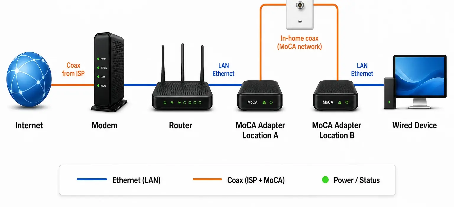
The important detail: this simple picture is only showing the logical path. In a real cable-internet home, the PoE filter still belongs upstream at the cable entry point or first splitter, while both MoCA adapters stay downstream on the in-home coax side. If a filter sits between the adapters, it blocks the MoCA link you are trying to create.
Diagram 2: fiber internet + coax used only inside the house
Fiber homes often have an ONT instead of a cable modem. In that case, the coax may be unused by the provider — which can be perfect for MoCA backhaul if the coax outlets still meet at a splitter or panel.
Internet handoff
Fiber ONT → Ethernet → router. The ISP is out of the coax picture here, so your coax is just an in-home transport path.
MoCA bridge
Router LAN → MoCA adapter → coax wall jack → splitter/panel → remote coax jack → second MoCA adapter.
Remote room
Second MoCA adapter → Ethernet → mesh node, switch, access point, or PC in the far room.
Why fiber is simpler: because the provider is not using the coax for internet delivery, you usually have fewer splitter/filter conflicts to work around. You still need the target rooms on the same coax tree.
With fiber, a PoE filter is not always required for provider isolation, but it can still be useful at the edge of your coax plant in apartments, condos, and any setup where coax might be shared or reconnected later. For the full fiber-specific decision path, use MoCA with fiber internet.
If the remote room has a coax plate but the adapter never links, troubleshoot the coax outlet that is not working for MoCA before replacing adapters or mesh nodes.
Diagram 3: MoCA backhaul for a mesh node
For mesh, think of MoCA as the wire that replaces a weak wireless hop. The mesh system still handles roaming and one network name; MoCA just gives the satellite node a cleaner path back to the router.
Router side
Router LAN → MoCA adapter → coax jack. If your gateway has built-in MoCA LAN, you may use that instead of a separate main adapter, but do not create two competing MoCA bridges.
Remote room
Coax jack → MoCA adapter → Ethernet → mesh satellite. Place the satellite in open air, not hidden inside the same cabinet as the coax plate.
Coax middle
Use MoCA-rated splitters and avoid amps that block MoCA frequencies. If the link light never appears, the coax path is probably split, filtered, amplified, or disconnected.
What the mesh node should actually see
- A live Ethernet handoff from the remote MoCA adapter.
- The node reporting wired backhaul in the mesh app, not wireless uplink.
- Open-air placement for the node, even if the coax plate is low on the wall.
Parts shown in the diagram
| Part | What it does | Common mistake |
|---|---|---|
| Two MoCA adapters | Convert Ethernet ↔ coax at each end | Buying only one adapter when the router/gateway does not already provide MoCA LAN |
| MoCA-rated splitter | Passes MoCA frequencies between coax runs | Leaving an old 5–1000 MHz splitter in the main panel |
| PoE MoCA filter | Keeps MoCA inside your home and can improve signal reflection | Installing it on the wrong branch between adapters |
| Ethernet patch cables | Connect router, adapter, switch, or mesh node | Using a bad cable and blaming the coax |
| Optional switch | Adds ports at the remote room | Putting the switch before the MoCA adapter on the wrong side of the link |
Where the PoE filter goes in the diagram
On a cable internet setup, the usual placement is:
- Best: on the incoming cable line before the first splitter.
- Also common: on the input port of the first splitter.
- Avoid: on an output leg that sits between your two MoCA adapters.
If your main question is filter location, use the deeper MoCA PoE filter placement guide. If your question is what splitter/filter to buy, use MoCA splitters and PoE filters.
How to sanity-check your own coax diagram
- Draw every coax outlet you want to use.
- Find the main splitter or structured media panel.
- Trace whether the router room and remote room are on the same splitter tree.
- Mark any amps, satellite gear, old splitters, or mystery filters.
- Replace obvious non-MoCA splitters before blaming the adapters.
- Test two adapters in the same room first if you are unsure the hardware works.
If the diagram does not match your house
Do not buy more mesh nodes yet. First decide whether your problem is coverage or backhaul. The Wi‑Fi dead zone fix plan will route you to mesh placement, MoCA, Ethernet, or troubleshooting based on the symptom.
If you already installed MoCA and the link is flaky, jump to MoCA troubleshooting.
Related next steps
- What is MoCA? — the plain-English explainer.
- MoCA for mesh Wi‑Fi — using coax for mesh backhaul.
- MoCA vs Ethernet vs Powerline — choose the right wired option.
- MoCA adapter picks — what to buy when your diagram is ready.
Before copying this topology, confirm how many MoCA adapters your layout needs; gateway MoCA, one remote room, and multi-room mesh backhaul use different counts.
Common Questions
How do I know whether moca wiring diagram: how to connect adapters, splitters, filters, and mesh is really my next step?
It is the right next step when it matches the physical bottleneck you can already describe: bad room placement, weak between-node hop, or clearly insufficient gear. The more specific the symptom, the more reliable the fix usually becomes.
Can I solve this without buying new hardware first?
Sometimes yes. NDZ generally wants you to measure, move, and validate before you spend, because a lot of dead-zone problems turn out to be layout problems first.
What should I read after this page?
Move toward measurement and troubleshooting, backhaul, or mesh guidance depending on what still feels unresolved.